Buchla inspired track. This started from exploration of Allen Stranges patch number 21.

This Blog is about electronic music, synthesizers and SDIY. Sigma-music can be found on Bandcamp (http://sigma2.bandcamp.com/), CDBaby and several other web streaming/downloading services.
sunnuntai 27. lokakuuta 2019
lauantai 26. lokakuuta 2019
Buchla 208 summa summarum
There was only one thing that didn't work as supposed in this build. Sequencer didn't operate correctly in the 3-stage mode (it worked as a 2 step sequence). 4 and 5 step stages worked ok. I changed the 4009 CMOS chip and after that everything worked as supposed!
Complex oscillators coarse slider useful range was only about the first half travel. I made the ModularSynthesis modification and added a 82k series resistor with R45 to reduce the gain of the coarse slider. That fixed this problem.
This build cost me about 2100€. Building was fun and the documentation in ElectricMusicStore, ModularSynthesis, Muff Wiggler and PortaBellabz helped a lot.
sunnuntai 20. lokakuuta 2019
Buchla Bongo-box
I made a programming card where random-voltage changes sequencers last step (just one resistor). This way the 5-step sequencer sounds like a longer sequencer and is more interesting. I also switched both lopass-gates serial (signal routing). There is internally a 180-degrees phase-shift between them so when I in the middle of this clip rise the LPG2-level same as the LPG1-level there happens some random phase-cancellations (random voltage opens the LPG2). This sounds like a delay or velocity control. There is no external effect in this clip. Just the internal spring-reverb.
perjantai 18. lokakuuta 2019
Metaprogramming the Electro Organism
I haven't enough banana cables so it is a good time to test the programming card. In Allen Stranges Buchla Easel manual there is a self-generating patch number 21.

I made a programming that based in this patch. Buchla is in both-mode (prog board + front panel). Random-voltage controls number-of-sequencer-steps, envelope-attack/decay and MO-modulation-mode.Sequencer controls MO-frequency and envelope generator controls lopass-gate1-level. Remaining connections are made with banana-cables. I adjusted the faders to my taste and here is the resulting sound-video.

I made a programming that based in this patch. Buchla is in both-mode (prog board + front panel). Random-voltage controls number-of-sequencer-steps, envelope-attack/decay and MO-modulation-mode.Sequencer controls MO-frequency and envelope generator controls lopass-gate1-level. Remaining connections are made with banana-cables. I adjusted the faders to my taste and here is the resulting sound-video.
torstai 17. lokakuuta 2019
Buchla calibration
Now Buchla is roughly in tune (1V/Oct) and calibrated. I changed R3 from 10k to 8.2k. This slighty decreases timbre folding and helped the calibration. The trickiest part was to balance the CO-timbre (motherboard TR4) and CO-waveshape (motherboard TR7) with Card9's TR5 (CO low freq track). The problem was to get pure sine-waveshape from bottom to top without any extra oscillations when applying the maximum timbre fold.
I calibrated CO and MO to 1V/Oct with trimmers TR8 and TR9 on motherboard. External CV must be connected to voltage input from keyboard banana-jack. Here is one sound example with long attack/decay times and with random AM-modulation of CO. Some external reverb is used.
I calibrated CO and MO to 1V/Oct with trimmers TR8 and TR9 on motherboard. External CV must be connected to voltage input from keyboard banana-jack. Here is one sound example with long attack/decay times and with random AM-modulation of CO. Some external reverb is used.
keskiviikko 9. lokakuuta 2019
Buchla is alive!
It's alive and creating sounds! Next I start to calibrate it. At the same time I check that everything is working. I love the outlook of this thing. It's like a synthesist's candy.
 |
| Colors of the sound! |
 |
| Here in the middle are the calibration trimmers of motherboard. |
sunnuntai 29. syyskuuta 2019
Buchla front panel and motherboard
I found the front panel from The Beast. Everything fits great and this starts to look like a Buchla 208. Next I must finish the motherboard so that I can start to solder the banana jacks.


torstai 29. elokuuta 2019
Buchla 208 status and the motherboard
All 12 cards are now ready. Next I will start the assembly of motherboard.

Following traces has been added to this 2.1 version of motherboard PCB:
- trace between Molex 4A and Molex 3B
- trace between Program Card pin7 and via
- trace to Card 8 pin 11 instead of pin 12 is corrected by connecting these two pins on motherboard
- trace between SW8 and SW10
To change the trigger threshold (Pulser, Sequencer, Envelope Generator) from 10V to 5V I will change R56 to 150k.
To enable my 208 to communicate with iProgram card I must do the following modifications:
- connectors B and 2 are connected together and grounded to Q (quiet/analog ground)
- pin C is connected to +5V
- pins D and 4 are connected together and grounded to N (noisy/digital ground)
I have cloned this motherboard (and all the cards) with all the corrections. Maybe I will build some day another 208 from my own PCBs.


Following traces has been added to this 2.1 version of motherboard PCB:
- trace between Molex 4A and Molex 3B
- trace between Program Card pin7 and via
- trace to Card 8 pin 11 instead of pin 12 is corrected by connecting these two pins on motherboard
- trace between SW8 and SW10
To change the trigger threshold (Pulser, Sequencer, Envelope Generator) from 10V to 5V I will change R56 to 150k.
To enable my 208 to communicate with iProgram card I must do the following modifications:
- connectors B and 2 are connected together and grounded to Q (quiet/analog ground)
- pin C is connected to +5V
- pins D and 4 are connected together and grounded to N (noisy/digital ground)
 |
| Photo by Modular Synthesis |

keskiviikko 28. elokuuta 2019
Buchla Card 12
I replaced the original Buchla Output-card with Boops Card 12 replacement. The reverb circuit is here better designed by driving the tank with current instead of voltage. I used the Davebr BOM from ModularSynthesis. With this card it is possible to bring out the MO and CO separately but I think I am not going to do this and I must jumper edge pins 7 and 9, let's see.
 |
| TOP |
 |
| BOTTOM |
tiistai 27. elokuuta 2019
Buchla Card 11
Card 11 is the LPG2. I changed C4 from 1uF to 47uF. This allows lower frequency MO (modulation oscillator) modulation of CO (complex oscillator). I also matched the vactrols VT1 and VT2.


sunnuntai 25. elokuuta 2019
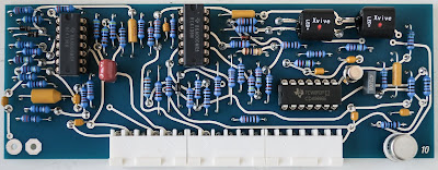
Buchla Card 10
Card 10 contains the Preamplifier and LPG-1. Vactrols VT1 and VT2 needs to be matched. In electro-music forum I found an other matching method where vactrols are connected in series and LDRs form a voltage divider between +V and -V. In theory the more similar vactrols are the closer to 0V the output will be. Pulse LFO worked the best and I managed to match to pairs of vactrols for Card 10 and 11. I cross-checked this to the first matching method with Card 5 and these give similar results.

 |
| Vactrol matching. |
perjantai 23. elokuuta 2019
Buchla Card 9
Card 9 is the last one of the three Complex Oscillator cards. No modifications in this card.

Now I have done 75% of this card show (Cards 1-9). So only three cards is left. Then I can populate the motherboard PCB.

 |
| Buchla flower |
torstai 22. elokuuta 2019
Buchla Card 8
Card 8 is the Complex Oscillator (Part 2). I matched diodes D1/D2, resistors R36/R37 and resistors R38/R39. The better these match the better the sine-shaper works. Pin 11/12 error is corrected in V2.1 motherboard PCB so there is no need to correct it in here. Capacitor C1 defines the frequency range of CO (lower values shift the range upwards). I leaved the C1 as it is in the original 208.


maanantai 19. elokuuta 2019
Buchla Card 7
Card 7 is the first in Complex Oscillator series (Cards 7-9). Some resistor values needs tweaking. I changed R14 from 120k to 68k for 1V/oct tracking. R46 value depends on VT2 variations, so this can be anything between 15k and 1k. I changed R3 from 1.8k to 10k which is the original value in schematics. I installed also another uA726 replacement pcb on this card.


torstai 15. elokuuta 2019
Buchla Card 6
Card 6 is the Modulation Oscillator. There is one jumper wire. I matched the two 2N3565 NPN transistors with Ian Fritz circuit. Kassutronics has also a good article about this matching method. I managed to match these transistors within 0.5mV (Vbe). There are a couple of resistors that needs to be determined empirically. I changed R5 from 190k to 82k to tune MO to 1V/oct. I also changed R9 from 240k to 330k to rise the MO base frequency. When I calibrate MO I can see if these values are ok. The uA726 is replaced with my mA726 PCB.

 |
| Matching 2N3565 transistors. |

sunnuntai 11. elokuuta 2019
Buchla Cards 1-5
Almost halfway with the 12 cards. Nothing special with card 2 (Random Voltage). This card has one jumper wire.

Cards 3 (Envelope Generator) and 4 (Pulser) can have problems with bleed into the audio. This is caused mainly by LEDs that take a lot of current. I cut the traces on bottom side to the driver transistors 2N1711 and soldered 1k resistors across the cuts to drop the currents. In card 3 I also added a 100pF capacitor across IC1 pins 12 and 14 to tame possible oscillations. Card 3 has two jumper wires.

Card 5 (Balanced Modulator) has seven vactrols. Vactrols 1/2, 3/4 and 5/6 need to be matched. With this simple test-circuit I measured the on-resistance of the LDR.


Resistance keeps rising as long as the LED is on. This is because the LED warms the LDR and this changes the resistance. I measured the lowest resistance when the vactrol was fired on. On REV2.1 cards there is a small pad added that indicates where the positive (+) lead of the vactrols LED should be inserted.

sunnuntai 4. elokuuta 2019
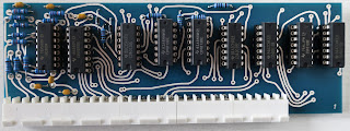
Buchla 208 Sequencer
Nothing special in this card. I added the decoupling capacitors to the bottom side to ensure trouble-free operation of the sequencer.


tiistai 23. heinäkuuta 2019
Buchla 208 clone

maanantai 8. heinäkuuta 2019

tiistai 11. kesäkuuta 2019
Moog Prodigy and AS3046
With these SOIC to DIP adapters I managed to change the LM3046 chips with AS3046 SMD drop-in replacement chips. Next I must re-calibrate Prodigy and see how these SMD-chips behave.


tiistai 4. kesäkuuta 2019
mA726
Here is my version of drop-in replacement for uA726 part used in Buchla Easel. I have tested this before here. I ordered the first proto-batch from Eurocircuits. Because of two SMD-parts it's very compact (width = 37mm and height = 17mm). For LM3046 replacement I use ALFA-parts AS3046 (Vbe is matched five times better for the NPN pair than in the original with +- 1mV).


keskiviikko 1. toukokuuta 2019
Buchla 208
I am considering the possibility to make my own clone of Buchla 208. Here is the first sketch of the motherboard.


sunnuntai 3. maaliskuuta 2019
Review of Sonic Landscapes
Here is a Sonic Immersion's review of my latest album Sonic Landscapes.
http://www.sonicimmersion.org/manu-sonic-landscapes/

http://www.sonicimmersion.org/manu-sonic-landscapes/

lauantai 12. tammikuuta 2019
Eventide H3000-D/SE
Finally found replacement part (jog wheel optical encoder) for my H3000. Adjusting any parameters was impossible when the jog wheel operated erractically. Optical encoder is an obsolete part that Eventide no longer stocks. Studio Electronics Inc. has this part ! It's little bit tricky to replace but I managed to do it and now the jog wheel operates normally.

 |
| Mechanical jog wheel with the optical encoder (led + LDR). |
 |
| Lot of old logic chips inside the H3000 ! |

Tilaa:
Blogitekstit (Atom)