torstai 29. elokuuta 2019

Buchla 208 status and the motherboard

All 12 cards are now ready. Next I will start the assembly of motherboard.


Following traces has been added to this 2.1 version of motherboard PCB:

- trace between Molex 4A and Molex 3B
- trace between Program Card pin7 and via
- trace to Card 8 pin 11 instead of pin 12 is corrected by connecting these two pins on motherboard
- trace between SW8 and SW10

To change the trigger threshold (Pulser, Sequencer, Envelope Generator) from 10V to 5V I will change R56 to 150k.

To enable my 208 to communicate with iProgram card I must do the following modifications:

- connectors B and 2 are connected together and grounded to Q (quiet/analog ground)
- pin C is connected to +5V
- pins D and 4 are connected together and grounded to N (noisy/digital ground)

Photo by Modular Synthesis
I have cloned this motherboard (and all the cards) with all the corrections. Maybe I will build some day another 208 from my own PCBs.


keskiviikko 28. elokuuta 2019

Buchla Card 12

I replaced the original Buchla Output-card with Boops Card 12 replacement. The reverb circuit is here better designed by driving the tank with current instead of voltage. I used the Davebr BOM from ModularSynthesis. With this card it is possible to bring out the MO and CO separately but I think I am not going to do this and I must jumper edge pins 7 and 9, let's see.

TOP

BOTTOM

tiistai 27. elokuuta 2019

Buchla Card 11

Card 11 is the LPG2. I changed C4 from 1uF to 47uF. This allows lower frequency MO (modulation oscillator) modulation of CO (complex oscillator). I also matched the vactrols VT1 and VT2.


sunnuntai 25. elokuuta 2019

Buchla Card 10

Card 10 contains the Preamplifier and LPG-1. Vactrols VT1 and VT2 needs to be matched. In electro-music forum I found an other matching method where vactrols are connected in series and LDRs form a voltage divider between +V and -V. In theory the more similar vactrols are the closer to 0V the output will be. Pulse LFO worked the best and I managed to match to pairs of vactrols for Card 10 and 11. I cross-checked this to the first matching method with Card 5 and these give similar results.


Vactrol matching.


perjantai 23. elokuuta 2019

Buchla Card 9

Card 9 is the last one of the three Complex Oscillator cards. No modifications in this card.


Now I have done 75% of this card show (Cards 1-9). So only three cards is left. Then I can populate the motherboard PCB.

Buchla flower

torstai 22. elokuuta 2019

Buchla Card 8

Card 8 is the Complex Oscillator (Part 2). I matched diodes D1/D2, resistors R36/R37 and resistors R38/R39. The better these match the better the sine-shaper works. Pin 11/12 error is corrected in V2.1 motherboard PCB so there is no need to correct it in here. Capacitor C1 defines the frequency range of CO (lower values shift the range upwards). I leaved the C1 as it is in the original 208.


maanantai 19. elokuuta 2019

Buchla Card 7

Card 7 is the first in Complex Oscillator series (Cards 7-9). Some resistor values needs tweaking. I changed R14 from 120k to 68k for 1V/oct tracking. R46 value depends on VT2 variations, so this can be anything between 15k and 1k. I changed R3 from 1.8k to 10k which is the original value in schematics. I installed also another uA726 replacement pcb on this card.


torstai 15. elokuuta 2019

Buchla Card 6

Card 6 is the Modulation Oscillator. There is one jumper wire. I matched the two 2N3565 NPN transistors with Ian Fritz circuit. Kassutronics has also a good article about this matching method. I managed to match these transistors within 0.5mV (Vbe). There are a couple of resistors that needs to be determined empirically. I changed R5 from 190k to 82k to tune MO to 1V/oct. I also changed R9 from 240k to 330k to rise the MO base frequency. When I calibrate MO I can see if these values are ok. The uA726 is replaced with my mA726 PCB.

Matching 2N3565 transistors.


sunnuntai 11. elokuuta 2019

Buchla Cards 1-5

Almost halfway with the 12 cards. Nothing special with card 2 (Random Voltage). This card has one jumper wire.


Cards 3 (Envelope Generator) and 4 (Pulser) can have problems with bleed into the audio. This is caused mainly by LEDs that take a lot of current. I cut the traces on bottom side to the driver transistors 2N1711 and soldered 1k resistors across the cuts to drop the currents. In card 3 I also added a 100pF capacitor across IC1 pins 12 and 14 to tame possible oscillations. Card 3 has two jumper wires.


Card 5 (Balanced Modulator) has seven vactrols. Vactrols 1/2, 3/4 and 5/6 need to be matched. With this simple test-circuit I measured the on-resistance of the LDR.


Resistance keeps rising as long as the LED is on. This is because the LED warms the LDR and this changes the resistance. I measured the lowest resistance when the vactrol was fired on. On REV2.1 cards there is a small pad added that indicates where the positive (+) lead of the vactrols LED should be inserted.


sunnuntai 4. elokuuta 2019

Buchla 208 Sequencer

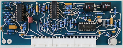
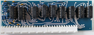
Nothing special in this card. I added the decoupling capacitors to the bottom side to ensure trouble-free operation of the sequencer.